
Both these rules are useful, but neither is precise enough to be used in all situations.
In order to determine exactly what multiple of inbound wind correction to use on the outbound leg, the dynamical equations for an aircraft in a hold were determined and solved (the math is shown at the end of this post).
The results are displayed in several graphical formats below.
The first graphical representation of required wind correction is in the below graph. In the below graph, when the term headwind or tailwind is used it always means that the headwind/tailwind is on the inbound leg.
 |
| Click to Enlarge |
It's interesting to note that as wind velocity approaches zero the required multiple approaches exactly 3, so the 3x inbound correction rule of thumb works well in light winds. Also of note, a headwind has a surprisingly large effect on the multiple required when combined with a crosswind.
The second graphical format is the below video which gives exact answers to to the question of required crosswind correction on the outbound leg for all possible integer valued wind directions and a wide range of wind velocities.
The final format is the below .gif which shows some of the same data as the videos, but in a format that is easier to share.

For the numerically inclined, a complete description of the problem and the equations used is given below.
FULL EXPLANATION OF THE PROBLEM AND EQUATIONS USED
IntroductionWhen operating an aircraft in instrument meteorological conditions (IMC), air traffic control will often require pilots to perform a maneuver called a “hold.” This maneuver requires the pilot to fly in a race-track shaped pattern in the sky as shown below:
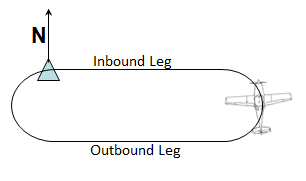
1. Making the inbound leg exactly 1 minute in length or 1.5 minutes if above 14,000 feet
2. After completing the turn from outbound leg to inbound leg, the aircraft should be tracking exactly towards the station (the station is represented by a greenish triangle above).
3. Constant indicated airspeed
4. When turning, the angular rate of turn should be exactly 3 degrees per second
5. Constant Altitude
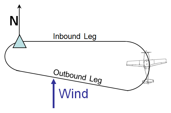
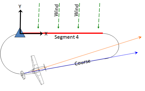
This maneuver is very simple in no-wind conditions, but, when there is a crosswind or headwind/tailwind or some combination thereof, achieving goals 1 and 2 can become difficult. When there is a crosswind, complying with goals 1 and 2 distorts the racetrack shape into a vaguely egg-shaped pattern as shown below:
Before continuing, it’s important to understand the difference between heading and course. Heading is the direction that the aircraft is pointed, an aircraft sitting on the ground will have a heading, it will be pointed in some direction. Course is the direction that an aircraft is traveling over the ground, it is the direction that a GPS device would tell you you are moving in if you are flying a GPS-equipped aircraft, a stationary aircraft on the ground does not have a course because it is not moving in any direction. If there is wind, there will usually be a difference between heading and course, the graphic below attempts to further clarify the difference between these two quantities.
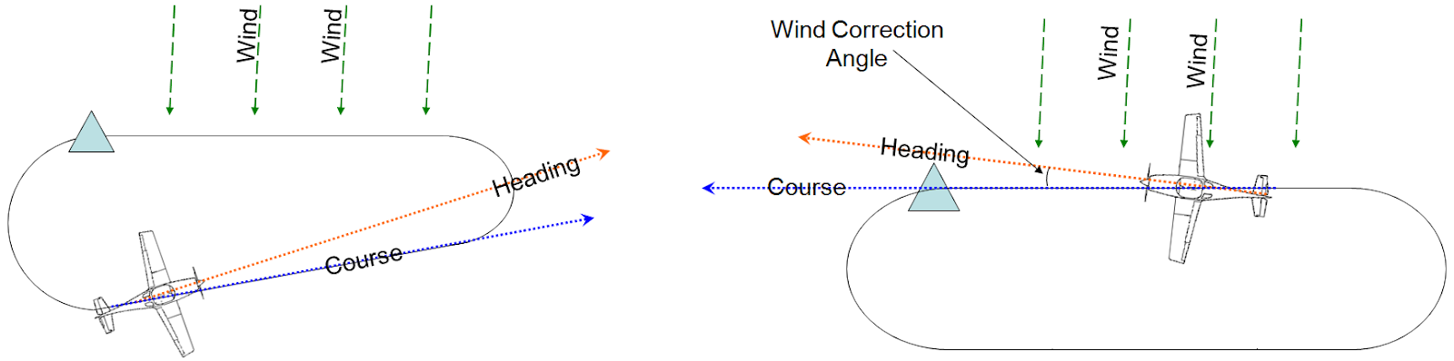
The technique that pilots use to achieve goal 2 when holding is to note the difference between course and heading when flying on the *inbound* leg of the hold, this difference is called the “wind correction angle.” Some multiple of this wind correction angle is then added to or subtracted from the aircraft’s no-wind heading when on the *outbound* leg. I’ve never met a pilot that knew exactly what this multiple should be, in undergrad I did some rough calculations and discovered that the multiple increases when the wind correction angle decreases and vice versa, I forget the exact equations I used but the result was that a multiple of 3 should be used when the wind correction angle is 5 degrees, 2.7 should be used when the angle is 10 degrees and 2 should be used when the angle is 20 degrees. If successful in finding the exact formula, I will find out how close these initial calculations were.
The technique that pilots use to achieve goal 1 is to vary the amount of time spent flying on the outbound leg, in no wind conditions the outbound leg is flown for exactly 1:00… But if there is a tailwind when on the inbound leg, more than one minute must be spent on the outbound and if there is a headwind on the inbound leg, less than one minute must be spent on the outbound leg. The rule of thumb used by pilots is to first fly one lap in the hold and add any missing time on the first inbound leg to the outbound leg or subtract any excess time on the inbound leg from the outbound leg. So if the first inbound leg took 1:10 the next outbound leg would be flown for 0:50. This method is obviously inexact as it breaks down in extreme conditions. For example, if on the inbound lag you had a headwind equal to 66.7% of your velocity and you started at a distance that in no wind conditions would result in the time being one minute it would take you 3 minutes to reach the station. In this case the excess time would be 2:00… but if you subtract 2:00 from the normal 1:00 outbound leg you get a negative time value... which is nonsensical.
In this post I will attempt to find an equation that gives the precise multiple that should be used to achieve goal 2 and the precise duration to be flown on the outbound leg to achieve goal 1. I will do this by finding the equation of motion for each of the 4 segments of the hold as functions of wind velocity and heading (with true airspeed held constant). These equations will then be solved for when goals 1 and 2 are met.
Preliminary Calculations
To start we need to find the exact relationship between rate of turn (which must be 3º/second) and bank angle. I will derive this relationship here starting from the equation for normal acceleration in the tangential-normal coordinate system and the equation for radius of turn as a function of bank angle, which will itself be derived from equations for centripetal force and acceleration. Wind is assumed to be constant in these calculations.
1. Finding the Radius of Turn vs. Bank Angle relationship
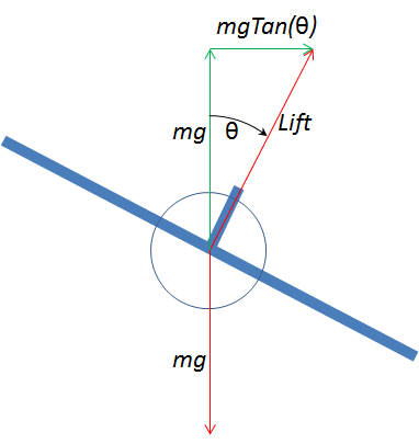
The formula for centripetal force is: mv^2/r, We are constrained to level flight per goal #5.
Setting the normal forces (the horizontal component of lift) to equal centripetal force we get:
mv^2/r = mgtan(θb)
r = v^2/gtan(θb) (1)
Where r is radius of turn
2. Finding the angle of bank which yields a 3 degrees per second rate of turn.
3 deg/second * pi/180 radians/degree = .05236 radians/second = dθb/dt
In the tangential-normal coordinate system:
F = ma
a = F/m
a = r (dθb/dt)^2 = F/m (2)
(v^2/gtan(θb))(.05236)^2 = mgtan(θb)/m
v^2/g2*.00274155=tan^2(θb)
tan(θb) = v/g*.05235983
θb = tan-1(v/g*.05235983)
Using 9.80m/s2 for g and and converting m/s to knots using the following conversion:
[6076ft/nautical mile]/[3600s/hr*3.28ft/m]
θb = tan-1((v/9.80)*[.05235983*6076/(3600*3.28)])
θb = tan-1(.00274925v) (3)
Wind does not affect TAS so in all turns for this problem the angle of bank will be:
tan-1(.00274925*100KTAS)= 15.372 degrees or .26829 radians
Setting up the Problem
There are three parts of the hold which are variable and one which is fixed:
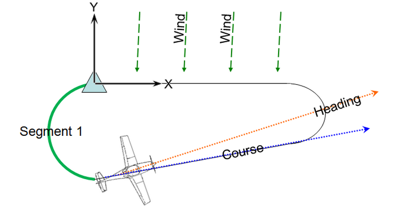
Segment 1 is variable, a constant 15.372 degree bank angle (assuming 100KTAS as in the example) will be held until such a time as the aircraft arrives at the desired heading for segment 2. In this problem we will assume that bank changes occur instantaneously though in reality changing bank from 15 degrees to 0 degrees takes about 2 seconds. Here we will try to determine the equation of motion for this portion of the hold in cartesian coordinates. For this problem we will set the zero degrees line to be parallel to the y axis as shown below, Additionally, because left turns in the hold are used in this example (and also in keeping with mathematical convention) *we will make angular displacement increase when traveling counterclockwise* as shown below, this is non-standard in aviation and could lead to confusion if not noted.

Acceleration here is all in the normal direction so the normal-tangential equation for acceleration:
a = r (dθ/dt)^2 + r(d2θ/dt^2)
becomes
a = r (dθ/dt)^2
The integral of this equation is velocity which is:
v= r(dθ/dt) +c1
In this case c1 is wind velocity, for this project we will use the variable w for wind velocity.
Integrating the above equation gives us position, here t1 represents the elapsed time in the first segment.
(x,y)= rθ +wt1 +c2
Here c2 represents our initial position, we will define the origin to be exactly at the station, therefore c2 is equal to the vector distance from the center of the turn to the station. The center of the turn is located at a distance equal to r in the direction (d) 90° left of heading, where heading is 0° + WCA therefore, d = 90° + WCA and c2 = rsin(WCA)i - rcos(WCA)j and heading at any given time will equal initial wind correction angle (WCA) plus θ degrees where θ = 3t,
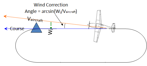
Initial wind correction angle is:
WCA = sin-1((wj)/(vaircraft-wi))
Because (dθ/dt) is a constant 3deg/s we can make this equation a cartesian function of time by substituting rθ for rcos(3t1)j - rsin(3t1)i and c2 for rsin(WCA)i - rcos(WCA)j:
(x,y)= rcos(3t1 +WCA)j - rsin(3t1 + WCA)i +wt1 + rsin(WCA)i -rcos(WCA)j (4)
Segment 2 is variable, desired heading and temporal duration vary with wind conditions. 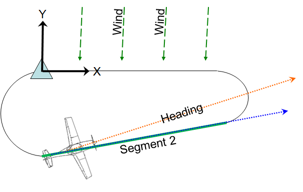
There is no acceleration during this leg, therefore: a = 0
Taking the integral:
Where c1 is equal to aircraft velocity vaircraft plus wind velocity w. The magnitude of the aircraft’s velocity is given as a state variable but the direction is determined by the duration for which segment 1 is flown, we will call this duration variable t1f, therefore:
and velocity can be stated as:
Taking the integral to get position:
Where t2 is the duration for which the second leg has been flown, c2 here represents the starting position which is the final position in segment 1 which is:
To simplify equations we will assign this expression the variable p1 therefore the equation for position for segment 2 is:
Segment 3 has constant bank angle and variable duration, it ends when the desired inbound heading is reached
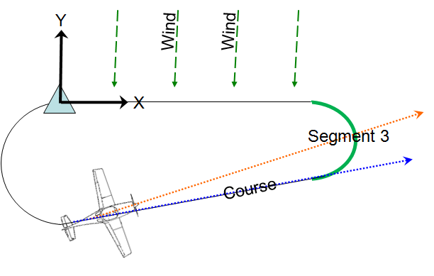
This segment is identical to segment 1 except for the beginning and end points and the degrees turned through, starting with the equation of motion:
The integral of this equation is velocity which is:
In this case c1 is wind velocity, for this project we will use the same variable w for wind.
Integrating the above equation gives us position, here t3 represents the elapsed time in the third segment.
The center of the turn is located at a distance equal to r in the direction (d2) 90° left of heading, where heading is H2 = WCA + t1f3°/s therefore, d2 = 90° + WCA + t1f3°/s and:
and c2 is equal to the position (p2) at the end of segment 2 plus the distance from that position to the center of the circle which is being turned:
There is no acceleration during this leg, therefore: a = 0
Taking the integral:
v = c1
Where c1 is equal to aircraft velocity vaircraft plus wind velocity w. The magnitude of the aircraft’s velocity is given as a state variable but the direction is determined by the duration for which segment 1 is flown, we will call this duration variable t1f, therefore:
H2 = 3t1f + sin-1(wj/vaircraft)
H2 = 3t1f + WCA (5)
and velocity can be stated as:
v = -vcos(3t1f + WCA)j + vsin(3t1f + WCA)i + w
Taking the integral to get position:
(x,y) = -vt2cos(3t1f +WCA)j - vt2sin(3t1f + WCA)i + wt2 + c2
(x,y)= rcos(3t1f)j -rsin(3t1f)i +wt1f -rsin(WCA)i -rcos(WCA)j
To simplify equations we will assign this expression the variable p1 therefore the equation for position for segment 2 is:
(x,y) = -vt2fsin(3t1f + WCA)j - vt2fcos(3t1f + WCA)i + wt2 + p1 (6)
Segment 3 has constant bank angle and variable duration, it ends when the desired inbound heading is reached
a = r (dθ/dt)^2
The integral of this equation is velocity which is:
v= r(dθ/dt) +c1
In this case c1 is wind velocity, for this project we will use the same variable w for wind.
Integrating the above equation gives us position, here t3 represents the elapsed time in the third segment.
(x,y)= rθ +wt3 +c2
The center of the turn is located at a distance equal to r in the direction (d2) 90° left of heading, where heading is H2 = WCA + t1f3°/s therefore, d2 = 90° + WCA + t1f3°/s and:
(x,y)= rcos(3t3 +H2)j - rsin(3t3 + H2)i +wt3 + c2
and c2 is equal to the position (p2) at the end of segment 2 plus the distance from that position to the center of the circle which is being turned:
c2 = p2 + rd2
To simplify equations we will assign this expression the variable p2 therefore the equation for position for segment 3 is:
(x,y)= rcos(3t3 +H2)j - rsin(3t3 + H2)i +wt3 + p2 + rd2(7)
Segment 4 is fixed, it must be flown for exactly 1 minute, because of this we know exactly where it must start and what direction it must be flown in, the direction is 090° and the distance is (vaircrafti + wi)/60min/hr which is equal to:
We will refer to this position as p3 for convenience.
Solving the Problem
Above we have expressions for position and heading in the first three segments, we will split each equation into a y component and an x component and state them below:
becomes:
And the equation of position for segment 2 which is:
becomes:
The equation of position for segment 3 is:
Which becomes: (note d2j becomes negative because the direction of displacement is downward.)
Now we will add all the x and y expressions by using the full equations for p1 and p2.
We can equate these two equations to the equation from segment 4:
Decomposed into directions:
This gives us 2 equations, but there are three unknowns: t1, t2, t3 so we need a constraint equation, because heading ends where it begins (a total of 360° turned), and rate of turn is constant at 3°/s we can determine that:
Therefore our constraint equation is:
A successful attempt to solve this 3x3 system of equations was made using MATLAB. Here is a link to the MATLAB ".m" file that will solve for the required wind correction on the inbound and outbound legs of a hold: Link. This code will not run unless you have the Symbolic Math Toolbox for MATLAB, additionally the latest revision of MATLAB caused an error, will debug when time permits.
For those who are unfamiliar with MATLAB I will try to create an interactive web app in the future but for now the video at the top will be your best resource.
(x,y) = 0j + vcos(WCA)i + wi (8)
We will refer to this position as p3 for convenience.
Above we have expressions for position and heading in the first three segments, we will split each equation into a y component and an x component and state them below:
(x,y)= rcos(3t1 +WCA)j - rsin(3t1 + WCA)i +wt1 + rsin(WCA)i -rcos(WCA)j
becomes:
(x)= - rsin(3t1 + WCA)i + wit1 + rsin(WCA)i = p1i
(y)= rcos(3t1 +WCA)j + wjt1 -rcos(WCA)j = p1j
(x,y) =- vt2fsin(3t1f + WCA)j - vt2fcos(3t1f + WCA)i+ wt2 + p1
becomes:
(x) = -vt2fcos(3t1f + WCA)i + wit2 + p1i = p2i
(y) = -vt2fsin(3t1f + WCA)j + wjt2 + p1j = p2j
The equation of position for segment 3 is:
(x,y)= rcos(3t3 + H2)j - rsin(3t3 + H2)i + wt3 + p2 + rd2
Which becomes: (note d2j becomes negative because the direction of displacement is downward.)
(x) = -rsin(3t3+H2)i + wit3 + rd2i + p2i
(y) =rcos(3t3 +H2)j + wjt3 - rd2j + p2j
Now we will add all the x and y expressions by using the full equations for p1 and p2.
(x) = rsin(WCA) - rsin(3t1f + WCA) + wit1f - vt2fcos(3t1f + WCA) + wit2f - rsin(3t3f + H2) + wit3f + rd2i (9)
(y) = rcos(3t1f + WCA) + wjt1f - rcos(WCA) - vt2fsin(3t1f + WCA)+ wjt2f + rcos(3t3f + H2) + wjt3f - rd2j (10)
We can equate these two equations to the equation from segment 4:
(x,y) = 0j + vcos(WCA)i + w
Decomposed into directions:
(x) = vcos(WCA)i + wi
(y) = 0j
This gives us 2 equations, but there are three unknowns: t1, t2, t3 so we need a constraint equation, because heading ends where it begins (a total of 360° turned), and rate of turn is constant at 3°/s we can determine that:
t1 + t3 = 360°/(3°/s)
Therefore our constraint equation is:
t1 + t3 = 120s (11)
A successful attempt to solve this 3x3 system of equations was made using MATLAB. Here is a link to the MATLAB ".m" file that will solve for the required wind correction on the inbound and outbound legs of a hold: Link. This code will not run unless you have the Symbolic Math Toolbox for MATLAB, additionally the latest revision of MATLAB caused an error, will debug when time permits.
For those who are unfamiliar with MATLAB I will try to create an interactive web app in the future but for now the video at the top will be your best resource.


